

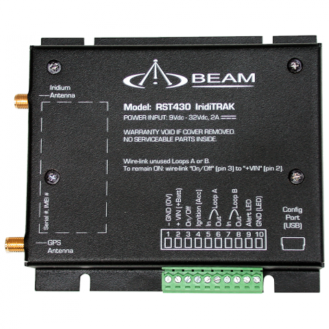
IridiTRAK - DISCONTINUED (RST430)
Beam Communications undertakes warranty and out of warranty servicing across our extensive product range.
For further information on our servicing process, warranty items and conditions please click on the button below.
Frequently Asked Questions
Powering Up/Restarting
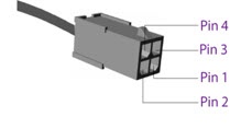
The pin out looking into the 4-way connector of the Docking Station (attached).
Only pins 1, 2 and 4 are used:
Pin 1 = Acc
Pin 2 = GND (0V)
Pin 4 = Constant Vin (+VE)
Firmware/Software/Configuration
To view the firmware version, use the relevant Beam Software Management tool available for download from the product support page.
To upgrade the firmware on your Beam docking station or terminal follow the steps below:
- Download the software management tool on the product support page.
- Install the software package on your computer.
- Connect the Beam docking station or terminal to the power supply.
- Connect the Beam docking station or terminal to the computer via USB or RS232 (whichever is applicable).
- Run the software management tool and follow the instructions on the screen.
- If your docking station or terminal is running an old version firmware, the software management tool will immediately recommend the update.
- If a fresh install of the tool does not recommend a firmware update, then your docking station or terminal is running the latest firmware.
Please ensure you have downloaded the latest version of the Beam Software Management tool from the product's support page.
The software management tool includes the required USB drivers to enable communication between the computer and the Beam docking station or terminal.
Also, refer to the Software Management tool's release note for operating system compatibility.
In addition please try the following process:
- Restart the PC
- Removing the USB cable from the device to the PC
- Power cycle the device
- Retry upgrading firmware
Signal/Connectivity
On a docking station/ terminal with status LED, the Status Led will change to green when the terminal is registered to the network.
For an RST100 terminal, the signal LED will change from Red to Green.
For Oceana/Terra 400 terminals, the signal LED on the terminal will change to GREEN (Good Signal Registered) or YELLOW (poor signal registered) when it is registered and able to make calls on the network.
Refer to the product's user manual for more information.
All wireless devices, including satellite telephones, are susceptible to RF (Radio Frequency) interference from other electronic devices. This problem is especially evident when numerous antennas and broadcasting devices are located within close proximity to each other.
A good example would be onboard a ship. It is important that certain considerations be taken into account for best performance when an Iridium/Inmarsat system is installed.
Causes of RF Interference:
Some subscribers have contacted Iridium regarding the loss of signal quality when they operate their equipment near active Inmarsat terminals. The power with which Inmarsat units transmit can overpower the Iridium unit’s ability to properly maintain a quality connection with the Iridium satellite constellation. Inmarsat terminals are often found in the same locations as Iridium subscribers, such as harbors, airports and especially onboard ships.
The location of the Inmarsat unit’s antenna in relation to the Iridium unit’s antenna plays a significant role in determining the degree of signal degradation that an Iridium subscriber can expect to experience. All Iridium units are susceptible to this interference, regardless of the type of antenna being used.
Generally speaking, an Iridium unit, be it a handset using its internal antenna or a fixed terminal when attached to an externally mounted antenna and located within 15 and 45 meters (50 to 150 feet, respectively) of an operating Inmarsat Standard-C terminal, will likely experience degraded performance.
Other sources of RF interference such as Globalstar units, radar devices and broadcast stations can provide interference for Iridium units, but usually are not encountered as frequently as Inmarsat terminals.
Also refer to “Assuring Quality of Iridium Service” in the Antenna Installation Guide.
Make sure the following are observed:
- Power supply level is steady and never fluctuates.
- Antenna is connected to the dock or terminal with a Beam approved cable.
- Antenna installation guide is followed.
- The sim is active, else request service provider to reset the service on the sim.
SBD
The IP Address is 12.47.179.11
directip.sbd.iridium.com / port 10800 which should resolve to 12.47.179.12:10800
Yes, the source IP address that will be utilized to connect to the Iridium gateway needs to be included within the Iridium network firewalls, to allow for successful connection.
This request for DMT access needs to be sent to the partners Iridium Account Manager.
Before an SBD can be sent, the LBT (in the Beam Device) or Iridium satellite phone must be provisioned for SBD. This includes Data being activated on your account and a destination address setup for the SBD to be sent to.
The destination address can be set to a specific IMEI number, an email address, or a direct IP Address / port.
Your service provider will be able to assist you in provisioning of your device.
Refer to the Beam Data Guide for more information on sending SBD's.
Messages sent to an ISU from the Host are sent to the email address: This email address is being protected from spambots. You need JavaScript enabled to view it.
- Placing at least one, and up to a total of four, IMEI(s) into the subject line of the email identifies the destination ISU(s).
- If there is more than one destination IMEIs then list the additional IMEIs on the subject line separated with a single space between each IMEI.
- White listing may be used to restrict the originator of MT-SBD messages to particular IMEIs. This restriction will fork for email and Direct IP.
- The message must contain a properly formatted sender (“From:” address), otherwise the message will be dropped by the GSS.
- The data message to the ISU must be carried as an attachment to the email:
- The attachment name must have a ‘.sbd’ file name extension: E.g. ‘importantdata.sbd’
- File names must be 80 characters or less. (Including the .sbd extension.)
- File names are not case sensitive.
- The maximum size of the binary message (not the Base64 version) is ISU specific and is between one byte and the maximum MT message size stated in Section 1.5
- The GSS will reject message sizes that are too large for a particular ISU type.
- The attachment must use standard Multipurpose Internet Mail Extensions (MIME) Base64 encoding as defined in RFC 2045.
- Multiple messages may be queued by a single email by including the additional separate attachments in the email message, subject to the maximum number of messages permitted in the queue.
- Note that if one of the attachments has an incorrect extension (.sbd), while others are correct then no error indication email will be sent.
- A single email with multiple attachments creates a MT-SBD message from each attachment. In other words – one email with ten attachments creates ten entries for the destination ISU.
- The message body plays no role in the message transfer process; any information contained in the body will be discarded.
- A maximum of 50 messages may be in any ISU’s queue at any one time regardless of whether they where sent as an individual message with attachment or a single message with multiple attachments. The GSS will reject any message over this limit.
The 9601 / 9602(N) / 9603(N) only supports Iridium's Short Burst Data (SBD) capability. It does not support voice, circuit switched data, or short message service (SMS).
Cables/Antennas
The proper torque for the sma connector is between 7 to 10 inch pounds of torque. (81 to 110 N-cm, for those who prefer metric measures).
If this value is exceeded, its possible to break the connector. Please note that if found the antenna connector has been damaged due to over tightening, this will void the warranty.
The maximum recommended signal drop from the passive satellite antenna to the Iridium transceiver( either a handset or Beam device) is 3dB. (Not applicable when using RST740).
For optimal performance, we recommend using the shortest length of cable and the fewest number of connectors possible. You must ensure that the cable used conforms to this.
An example of attenuation for RG213 cable is 0.33dB per metre @ 1.6Ghz, therefore the maximum cable length is 8m (allowing up to 0.5dB for cable interconnections).
LMR400 cable in comparison has a better attenuation figure of 0.18dB per metre.
Feel free to use the Beam Iridium Online Cable calculator to design your cable for a Beam Iridium docking station or terminal.
Important: This calculator is best viewed on desktop. Not optimised for mobile viewing.
To use the online Cable Calculator, use the following steps:
- Select the first Cable Type and Enter Length. -> Click Add Cable
- Select the connector on one end of the cable. -> Click Add Connector
- Select the connector on the other end of the cable. -> Click Add Connector
- Repeat for each Additional Cable or connector to get Total Loss in dB.
- Click Clear All to reset Loss calculations.
| Select cable type | Length (metres) | |
| Select connector type | ||
| Allowable Loss: 3dB | Loss dB | |
Manuals & Guides
User Manual RST430 IridiTRAK
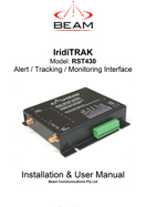
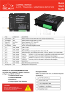
Quick Start Guide RST430 IridiTRAK
Configuration
To configure the settings and update the firmware on the docking station/terminal:
- Download and install the Software Management Tool to a compatible windows computer.
- When available, download and follow the Installation Guide.
- Make sure power is supplied to the docking station/terminal.
- With a Serial/USB cable, connect the docking station/terminal to the computer.
- Open the Software Management Tool and connect.
- For help on using the Software Management Tool, some have user manuals that is available to download from the tool itself by clicking on the ? or Help link.
Frequently Asked Questions
Powering Up/Restarting
The pin out looking into the 4-way connector of the Docking Station (attached).
Only pins 1, 2 and 4 are used:
Pin 1 = Acc
Pin 2 = GND (0V)
Pin 4 = Constant Vin (+VE)
Firmware/Software/Configuration
To view the firmware version, use the relevant Beam Software Management tool available for download from the product support page.
To upgrade the firmware on your Beam docking station or terminal follow the steps below:
- Download the software management tool on the product support page.
- Install the software package on your computer.
- Connect the Beam docking station or terminal to the power supply.
- Connect the Beam docking station or terminal to the computer via USB or RS232 (whichever is applicable).
- Run the software management tool and follow the instructions on the screen.
- If your docking station or terminal is running an old version firmware, the software management tool will immediately recommend the update.
- If a fresh install of the tool does not recommend a firmware update, then your docking station or terminal is running the latest firmware.
Please ensure you have downloaded the latest version of the Beam Software Management tool from the product's support page.
The software management tool includes the required USB drivers to enable communication between the computer and the Beam docking station or terminal.
Also, refer to the Software Management tool's release note for operating system compatibility.
In addition please try the following process:
- Restart the PC
- Removing the USB cable from the device to the PC
- Power cycle the device
- Retry upgrading firmware
Signal/Connectivity
On a docking station/ terminal with status LED, the Status Led will change to green when the terminal is registered to the network.
For an RST100 terminal, the signal LED will change from Red to Green.
For Oceana/Terra 400 terminals, the signal LED on the terminal will change to GREEN (Good Signal Registered) or YELLOW (poor signal registered) when it is registered and able to make calls on the network.
Refer to the product's user manual for more information.
All wireless devices, including satellite telephones, are susceptible to RF (Radio Frequency) interference from other electronic devices. This problem is especially evident when numerous antennas and broadcasting devices are located within close proximity to each other.
A good example would be onboard a ship. It is important that certain considerations be taken into account for best performance when an Iridium/Inmarsat system is installed.
Causes of RF Interference:
Some subscribers have contacted Iridium regarding the loss of signal quality when they operate their equipment near active Inmarsat terminals. The power with which Inmarsat units transmit can overpower the Iridium unit’s ability to properly maintain a quality connection with the Iridium satellite constellation. Inmarsat terminals are often found in the same locations as Iridium subscribers, such as harbors, airports and especially onboard ships.
The location of the Inmarsat unit’s antenna in relation to the Iridium unit’s antenna plays a significant role in determining the degree of signal degradation that an Iridium subscriber can expect to experience. All Iridium units are susceptible to this interference, regardless of the type of antenna being used.
Generally speaking, an Iridium unit, be it a handset using its internal antenna or a fixed terminal when attached to an externally mounted antenna and located within 15 and 45 meters (50 to 150 feet, respectively) of an operating Inmarsat Standard-C terminal, will likely experience degraded performance.
Other sources of RF interference such as Globalstar units, radar devices and broadcast stations can provide interference for Iridium units, but usually are not encountered as frequently as Inmarsat terminals.
Also refer to “Assuring Quality of Iridium Service” in the Antenna Installation Guide.
Make sure the following are observed:
- Power supply level is steady and never fluctuates.
- Antenna is connected to the dock or terminal with a Beam approved cable.
- Antenna installation guide is followed.
- The sim is active, else request service provider to reset the service on the sim.
SBD
The IP Address is 12.47.179.11
directip.sbd.iridium.com / port 10800 which should resolve to 12.47.179.12:10800
Yes, the source IP address that will be utilized to connect to the Iridium gateway needs to be included within the Iridium network firewalls, to allow for successful connection.
This request for DMT access needs to be sent to the partners Iridium Account Manager.
Before an SBD can be sent, the LBT (in the Beam Device) or Iridium satellite phone must be provisioned for SBD. This includes Data being activated on your account and a destination address setup for the SBD to be sent to.
The destination address can be set to a specific IMEI number, an email address, or a direct IP Address / port.
Your service provider will be able to assist you in provisioning of your device.
Refer to the Beam Data Guide for more information on sending SBD's.
Messages sent to an ISU from the Host are sent to the email address: This email address is being protected from spambots. You need JavaScript enabled to view it.
- Placing at least one, and up to a total of four, IMEI(s) into the subject line of the email identifies the destination ISU(s).
- If there is more than one destination IMEIs then list the additional IMEIs on the subject line separated with a single space between each IMEI.
- White listing may be used to restrict the originator of MT-SBD messages to particular IMEIs. This restriction will fork for email and Direct IP.
- The message must contain a properly formatted sender (“From:” address), otherwise the message will be dropped by the GSS.
- The data message to the ISU must be carried as an attachment to the email:
- The attachment name must have a ‘.sbd’ file name extension: E.g. ‘importantdata.sbd’
- File names must be 80 characters or less. (Including the .sbd extension.)
- File names are not case sensitive.
- The maximum size of the binary message (not the Base64 version) is ISU specific and is between one byte and the maximum MT message size stated in Section 1.5
- The GSS will reject message sizes that are too large for a particular ISU type.
- The attachment must use standard Multipurpose Internet Mail Extensions (MIME) Base64 encoding as defined in RFC 2045.
- Multiple messages may be queued by a single email by including the additional separate attachments in the email message, subject to the maximum number of messages permitted in the queue.
- Note that if one of the attachments has an incorrect extension (.sbd), while others are correct then no error indication email will be sent.
- A single email with multiple attachments creates a MT-SBD message from each attachment. In other words – one email with ten attachments creates ten entries for the destination ISU.
- The message body plays no role in the message transfer process; any information contained in the body will be discarded.
- A maximum of 50 messages may be in any ISU’s queue at any one time regardless of whether they where sent as an individual message with attachment or a single message with multiple attachments. The GSS will reject any message over this limit.
The 9601 / 9602(N) / 9603(N) only supports Iridium's Short Burst Data (SBD) capability. It does not support voice, circuit switched data, or short message service (SMS).
Cables/Antennas
The proper torque for the sma connector is between 7 to 10 inch pounds of torque. (81 to 110 N-cm, for those who prefer metric measures).
If this value is exceeded, its possible to break the connector. Please note that if found the antenna connector has been damaged due to over tightening, this will void the warranty.
The maximum recommended signal drop from the passive satellite antenna to the Iridium transceiver( either a handset or Beam device) is 3dB. (Not applicable when using RST740).
For optimal performance, we recommend using the shortest length of cable and the fewest number of connectors possible. You must ensure that the cable used conforms to this.
An example of attenuation for RG213 cable is 0.33dB per metre @ 1.6Ghz, therefore the maximum cable length is 8m (allowing up to 0.5dB for cable interconnections).
LMR400 cable in comparison has a better attenuation figure of 0.18dB per metre.
Feel free to use the Beam Iridium Online Cable calculator to design your cable for a Beam Iridium docking station or terminal.
Important: This calculator is best viewed on desktop. Not optimised for mobile viewing.
To use the online Cable Calculator, use the following steps:
- Select the first Cable Type and Enter Length. -> Click Add Cable
- Select the connector on one end of the cable. -> Click Add Connector
- Select the connector on the other end of the cable. -> Click Add Connector
- Repeat for each Additional Cable or connector to get Total Loss in dB.
- Click Clear All to reset Loss calculations.
| Select cable type | Length (metres) | |
| Select connector type | ||
| Allowable Loss: 3dB | Loss dB | |
Manuals & Guides
User Manual RST430 IridiTRAK
Quick Start Guide RST430 IridiTRAK
Configuration
To configure the settings and update the firmware on the docking station/terminal:
- Download and install the Software Management Tool to a compatible windows computer.
- When available, download and follow the Installation Guide.
- Make sure power is supplied to the docking station/terminal.
- With a Serial/USB cable, connect the docking station/terminal to the computer.
- Open the Software Management Tool and connect.
- For help on using the Software Management Tool, some have user manuals that is available to download from the tool itself by clicking on the ? or Help link.