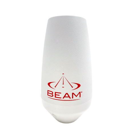
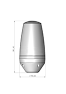
Beam Mast/Pole/Rail Mount Antenna (RST210)

Beam Communications undertakes warranty and out of warranty servicing across our extensive product range.
For further information on our servicing process, warranty items and conditions please click on the button below.
Frequently Asked Questions
Signal/Connectivity
All wireless devices, including satellite telephones, are susceptible to RF (Radio Frequency) interference from other electronic devices. This problem is especially evident when numerous antennas and broadcasting devices are located within close proximity to each other.
A good example would be onboard a ship. It is important that certain considerations be taken into account for best performance when an Iridium/Inmarsat system is installed.
Causes of RF Interference:
Some subscribers have contacted Iridium regarding the loss of signal quality when they operate their equipment near active Inmarsat terminals. The power with which Inmarsat units transmit can overpower the Iridium unit’s ability to properly maintain a quality connection with the Iridium satellite constellation. Inmarsat terminals are often found in the same locations as Iridium subscribers, such as harbors, airports and especially onboard ships.
The location of the Inmarsat unit’s antenna in relation to the Iridium unit’s antenna plays a significant role in determining the degree of signal degradation that an Iridium subscriber can expect to experience. All Iridium units are susceptible to this interference, regardless of the type of antenna being used.
Generally speaking, an Iridium unit, be it a handset using its internal antenna or a fixed terminal when attached to an externally mounted antenna and located within 15 and 45 meters (50 to 150 feet, respectively) of an operating Inmarsat Standard-C terminal, will likely experience degraded performance.
Other sources of RF interference such as Globalstar units, radar devices and broadcast stations can provide interference for Iridium units, but usually are not encountered as frequently as Inmarsat terminals.
Also refer to “Assuring Quality of Iridium Service” in the Antenna Installation Guide.
Make sure the following are observed:
- Power supply level is steady and never fluctuates.
- Antenna is connected to the dock or terminal with a Beam approved cable.
- Antenna installation guide is followed.
- The sim is active, else request service provider to reset the service on the sim.
Cables/Antennas
The maximum recommended signal drop from the passive satellite antenna to the Iridium transceiver( either a handset or Beam device) is 3dB. (Not applicable when using RST740).
For optimal performance, we recommend using the shortest length of cable and the fewest number of connectors possible. You must ensure that the cable used conforms to this.
An example of attenuation for RG213 cable is 0.33dB per metre @ 1.6Ghz, therefore the maximum cable length is 8m (allowing up to 0.5dB for cable interconnections).
LMR400 cable in comparison has a better attenuation figure of 0.18dB per metre.
Feel free to use the Beam Iridium Online Cable calculator to design your cable for a Beam Iridium docking station or terminal.
Important: This calculator is best viewed on desktop. Not optimised for mobile viewing.
To use the online Cable Calculator, use the following steps:
- Select the first Cable Type and Enter Length. -> Click Add Cable
- Select the connector on one end of the cable. -> Click Add Connector
- Select the connector on the other end of the cable. -> Click Add Connector
- Repeat for each Additional Cable or connector to get Total Loss in dB.
- Click Clear All to reset Loss calculations.
| Select cable type | Length (metres) | |
| Select connector type | ||
| Allowable Loss: 3dB | Loss dB | |
Manuals & Guides
RST210 Installation Guide
Frequently Asked Questions
Signal/Connectivity
All wireless devices, including satellite telephones, are susceptible to RF (Radio Frequency) interference from other electronic devices. This problem is especially evident when numerous antennas and broadcasting devices are located within close proximity to each other.
A good example would be onboard a ship. It is important that certain considerations be taken into account for best performance when an Iridium/Inmarsat system is installed.
Causes of RF Interference:
Some subscribers have contacted Iridium regarding the loss of signal quality when they operate their equipment near active Inmarsat terminals. The power with which Inmarsat units transmit can overpower the Iridium unit’s ability to properly maintain a quality connection with the Iridium satellite constellation. Inmarsat terminals are often found in the same locations as Iridium subscribers, such as harbors, airports and especially onboard ships.
The location of the Inmarsat unit’s antenna in relation to the Iridium unit’s antenna plays a significant role in determining the degree of signal degradation that an Iridium subscriber can expect to experience. All Iridium units are susceptible to this interference, regardless of the type of antenna being used.
Generally speaking, an Iridium unit, be it a handset using its internal antenna or a fixed terminal when attached to an externally mounted antenna and located within 15 and 45 meters (50 to 150 feet, respectively) of an operating Inmarsat Standard-C terminal, will likely experience degraded performance.
Other sources of RF interference such as Globalstar units, radar devices and broadcast stations can provide interference for Iridium units, but usually are not encountered as frequently as Inmarsat terminals.
Also refer to “Assuring Quality of Iridium Service” in the Antenna Installation Guide.
Make sure the following are observed:
- Power supply level is steady and never fluctuates.
- Antenna is connected to the dock or terminal with a Beam approved cable.
- Antenna installation guide is followed.
- The sim is active, else request service provider to reset the service on the sim.
Cables/Antennas
The maximum recommended signal drop from the passive satellite antenna to the Iridium transceiver( either a handset or Beam device) is 3dB. (Not applicable when using RST740).
For optimal performance, we recommend using the shortest length of cable and the fewest number of connectors possible. You must ensure that the cable used conforms to this.
An example of attenuation for RG213 cable is 0.33dB per metre @ 1.6Ghz, therefore the maximum cable length is 8m (allowing up to 0.5dB for cable interconnections).
LMR400 cable in comparison has a better attenuation figure of 0.18dB per metre.
Feel free to use the Beam Iridium Online Cable calculator to design your cable for a Beam Iridium docking station or terminal.
Important: This calculator is best viewed on desktop. Not optimised for mobile viewing.
To use the online Cable Calculator, use the following steps:
- Select the first Cable Type and Enter Length. -> Click Add Cable
- Select the connector on one end of the cable. -> Click Add Connector
- Select the connector on the other end of the cable. -> Click Add Connector
- Repeat for each Additional Cable or connector to get Total Loss in dB.
- Click Clear All to reset Loss calculations.
| Select cable type | Length (metres) | |
| Select connector type | ||
| Allowable Loss: 3dB | Loss dB | |


